CNC Example 09: Using Tool Length Correction
See the CNC09_ToolLengthCorr.project sample project in the installation directory of CODESYS under ..\CODESYS SoftMotion\Examples.
This example demonstrates how to use the SMC_ToolLengthCorr POU to compensate the length of a tool.
For more information about the topic of tool length correction, see: Preprocessing
Application
For the example, a Gantry3 kinematic is used together with an added orientation axis (AxisA) which can rotate about the Z axis. A tool with a length of 2 units in the Z direction is in turn attached to the orientation axis.
A simple CNC program should be run. This is stored in the project as an external CNC.cnc file and can be opened with a text editor. In the CNC program, the tool length correction is first activated by means of G code G43. The I, J, and K parameters correspond to the offset in the X, Y, and Z directions for this. Next, three points are traveled to in the XY plane. During the movement to the last point, the additional axis A is also rotated by 90 degrees.
N000 G43 I0 J0 K2 (Activate tool length correction with tool offset X=0 Y=0 Z=2)
N010 G01 X10 F10 E100 E-100
N020 G03 Y10 R5N030 G01 X0 A90
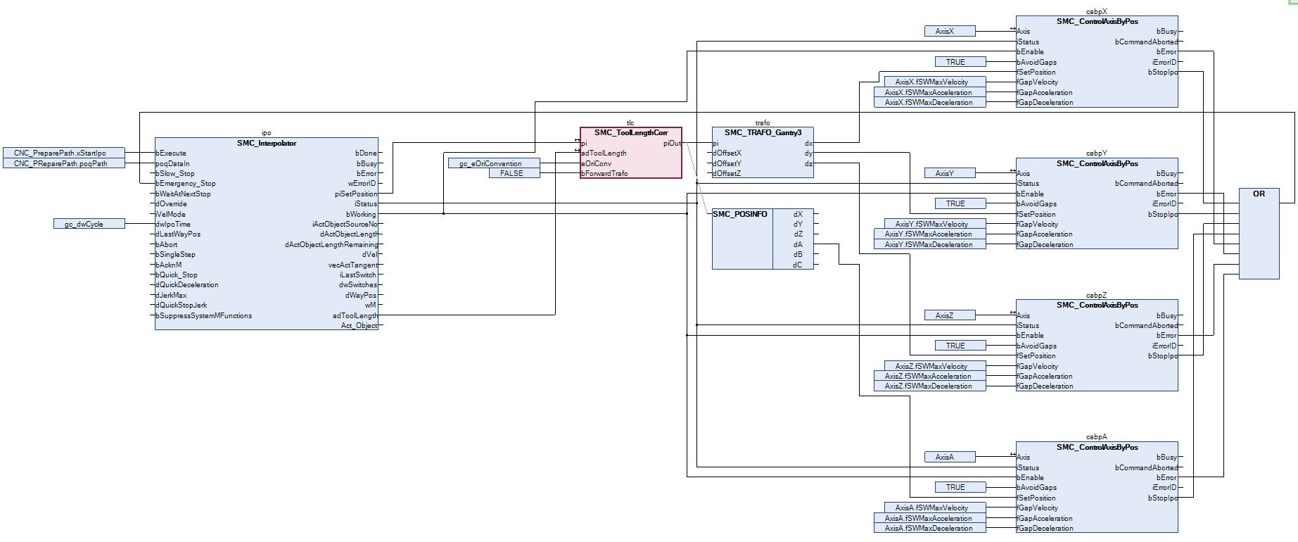
The application consists of multiple parts. In the CNC_PreparePath program, the CNC program CNC.cnc is imported as a file from the controller and preprocessed. In the CNC program, the drives are first switched on, as in the other examples. Then the interpolation of the previously read CNC program is performed. In each cycle, the interpolator outputs a set position (piSetPosition) and the current offset of the tool (adToolLength). The SMC_ToolLengthCorr POU requires this information to compensate the specified tool length. The compensated position is then transformed and finally passed to the axes by means of the SMC_ControlAxisByPos POUs.
Tip
The program is almost identical to the other examples. Only the SMC_ToolLengthCorr POU has been inserted after the interpolator and before the transformation in order to process the set position output by the interpolator.
Commissioning
Compile and start the created program. The program executes the CNC movement as soon as the CNC_PreparePath.xStart input has been set. You can click the Start button to set this variable in the application or in the visualization. After the program has run completely, you can apply a new rising edge to restart it.
During the execution of the CNC program, note the outputs of the interpolator (piSetPosition, adToolLength) and the compensated position (piOut) of the SMC_ToolLengthCorr POU.
Note: The rotation of AxisA during the last movement of the CNC program has no (additional) effect on the compensated Cartesian position in this example because the tool has only an offset in Z direction. If you add a component to the offset of the tool (in the CNC file, on the controller in the application folder) in X and Y direction, then the rotation of AxisA during the last movement will have an additional effect on the compensated position.